
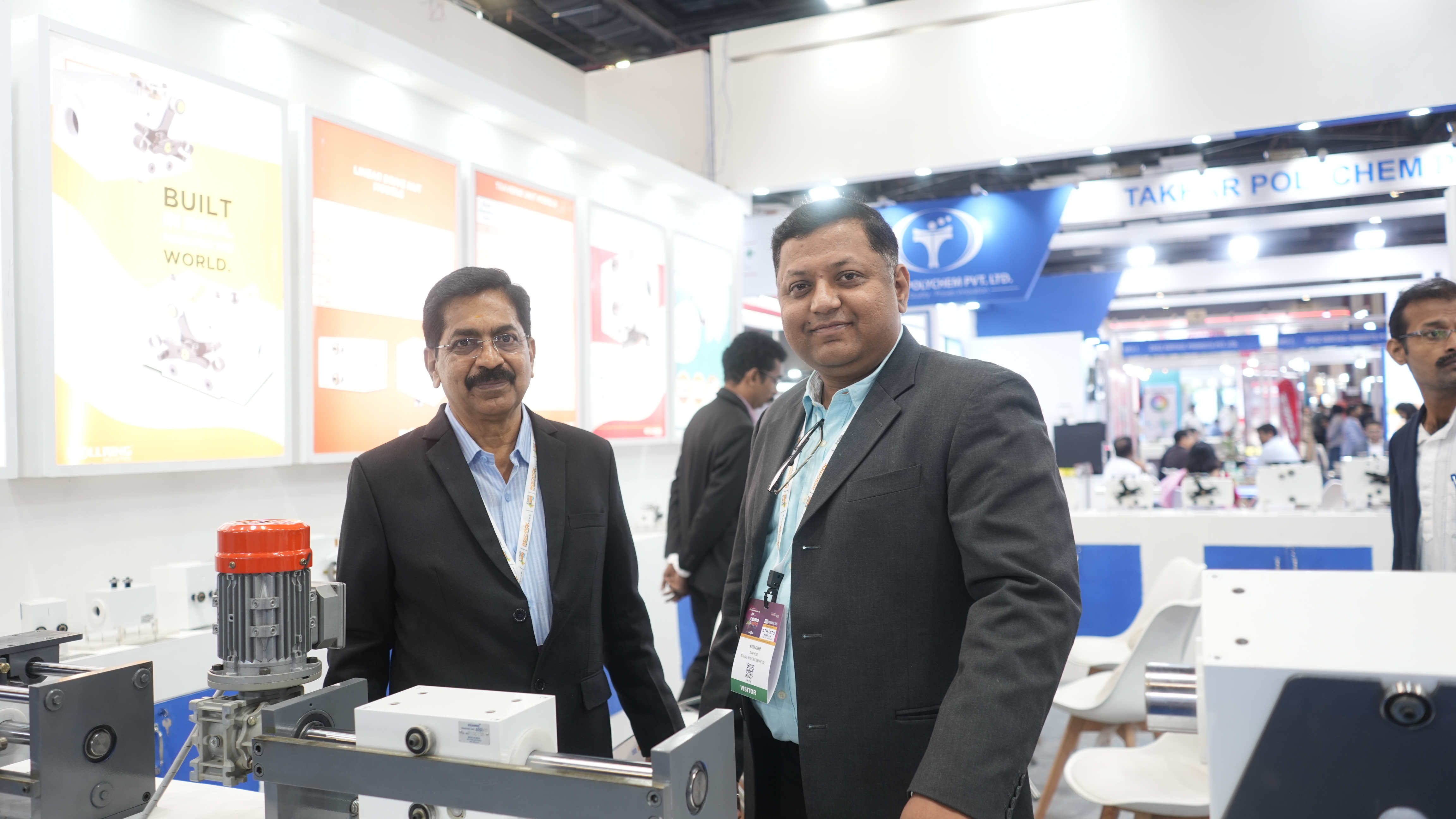
We are manufacture and exporters of Traverse Unit, Traverse assembly, Linear drives, Spooling Machine, Take up, Rewinding Lines, Winder for FRP line, Layer and Cross Over Winding machines for Transformer, Strip Winding and Vertical Take up.
R
O
L
L
R
I
N
G
- Your Trusted Partner in Traverse Units, Assemblies, and Linear Drives
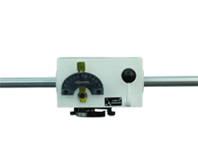
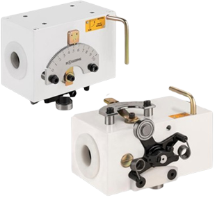
Traverse unit for 10 mm diameter shaft
(Model HT1)
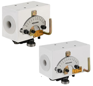
Traverse unit for 15 mm diameter shaft
(Model HT2 & 4RR15)
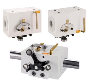
Traverse unit for 16 mm diameter shaft
(Model HT16 & 4RR16)
Traverse unit for 20 mm diameter shaft
(Model HT3 & 4RR20)
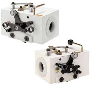
Traverse unit for 22 mm diameter shaft
(Model HT22 & 4RR22)
Traverse unit for 25 mm diameter shaft
(Model HT25 & 4RR25)
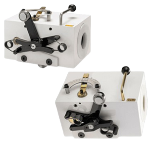
Traverse unit for 30 mm diameter shaft
(Model HT3N & 4RR30)
Traverse unit for 40 mm diameter shaft
(Model HT4 , 3RR40 & 4RR40 )
Traverse unit for 50 mm diameter shaft
(Model HT5 & 4RR50)
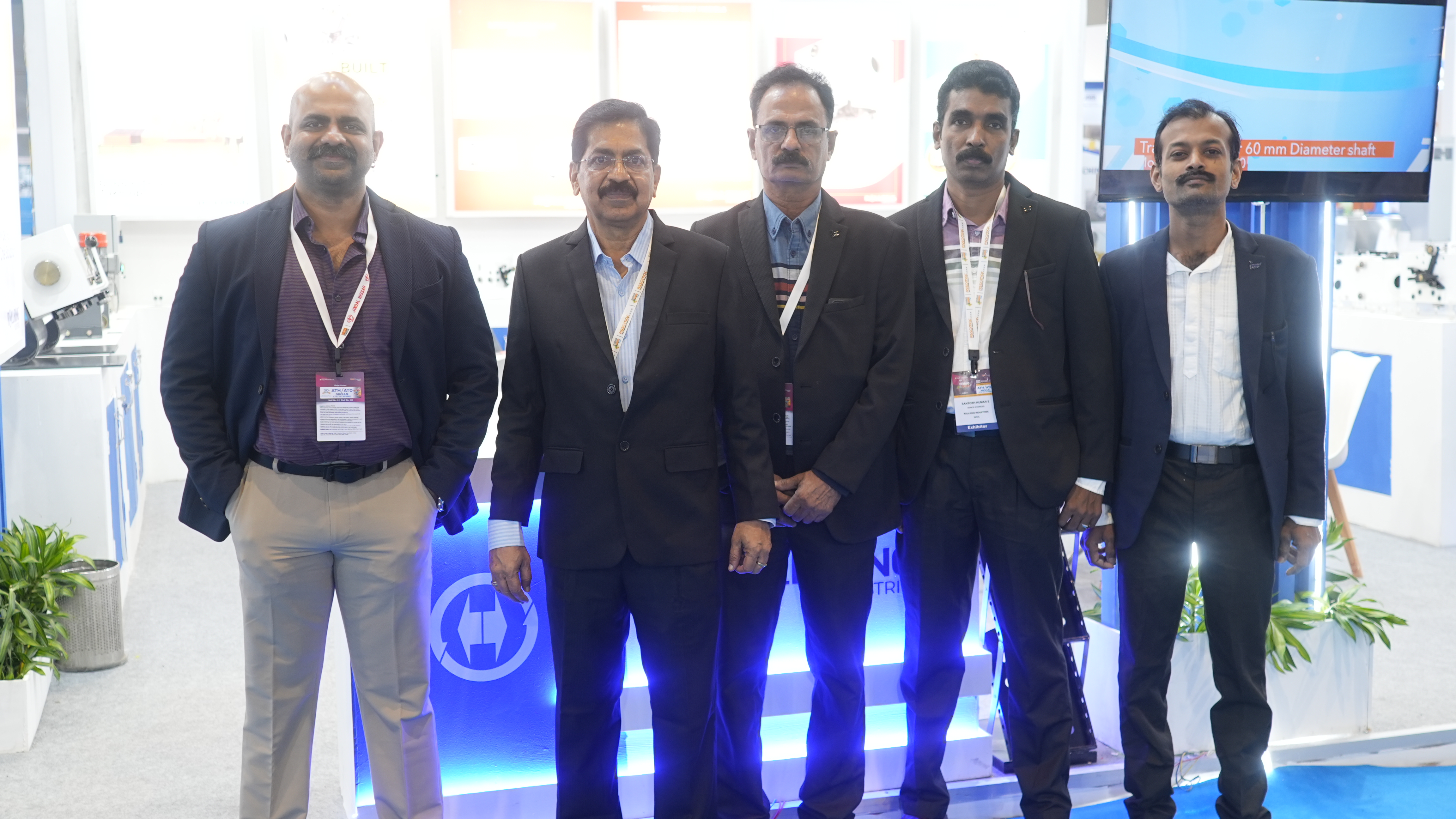
Traverse unit for 60 mm diameter shaft
(Model HT6 & 4RR60)
Traverse unit for 80 mm diameter shaft
(Model HT8 & 4RR80)
Our Product Range
We are involved as the manufacturer and exporter of an exclusive range of Winding Machine, Take Up Machine, Traverse Unit, Stainless Steel Strip and many more. We also render Winding Machine Repairing Service and Spooling Machine Repairing Service.
Rollring Industries
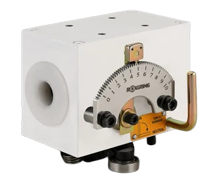
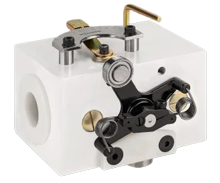
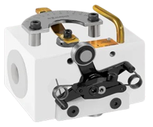
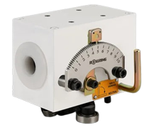
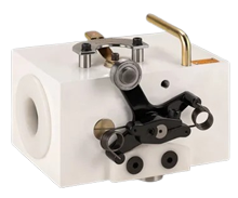
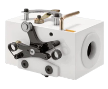
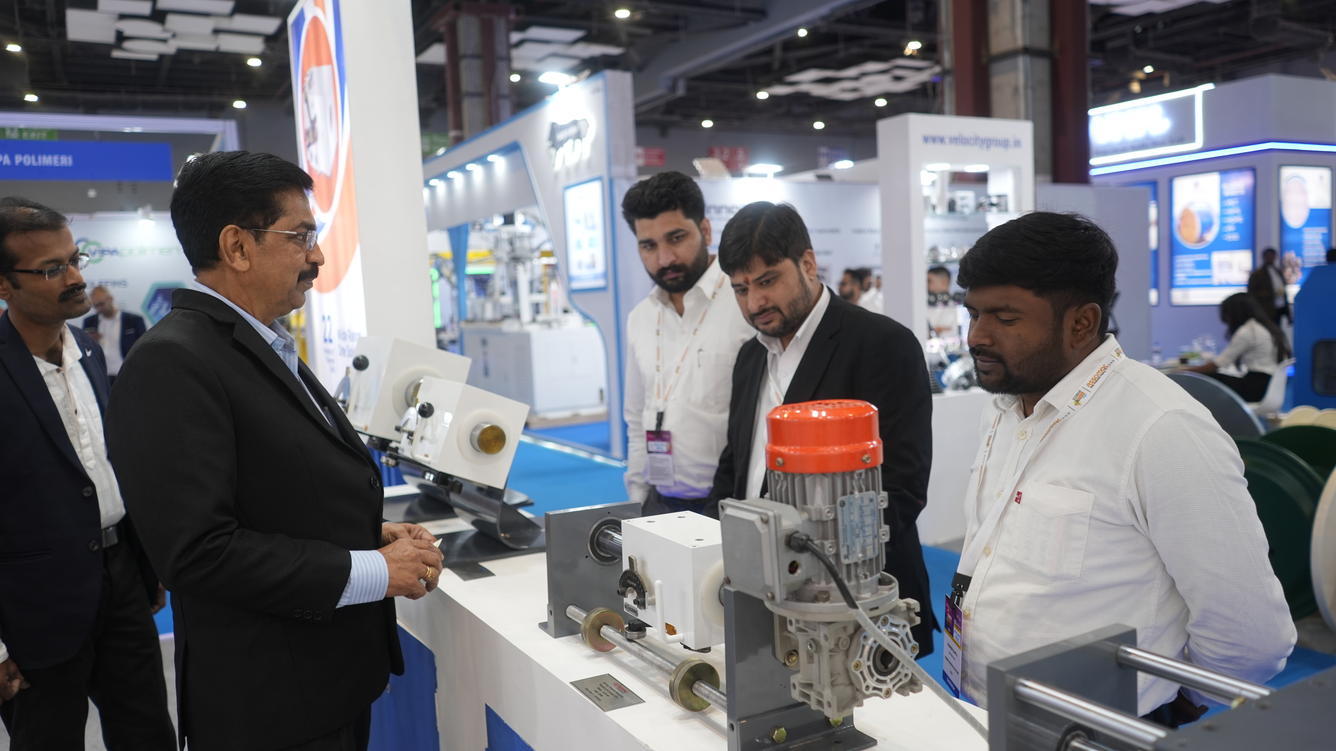
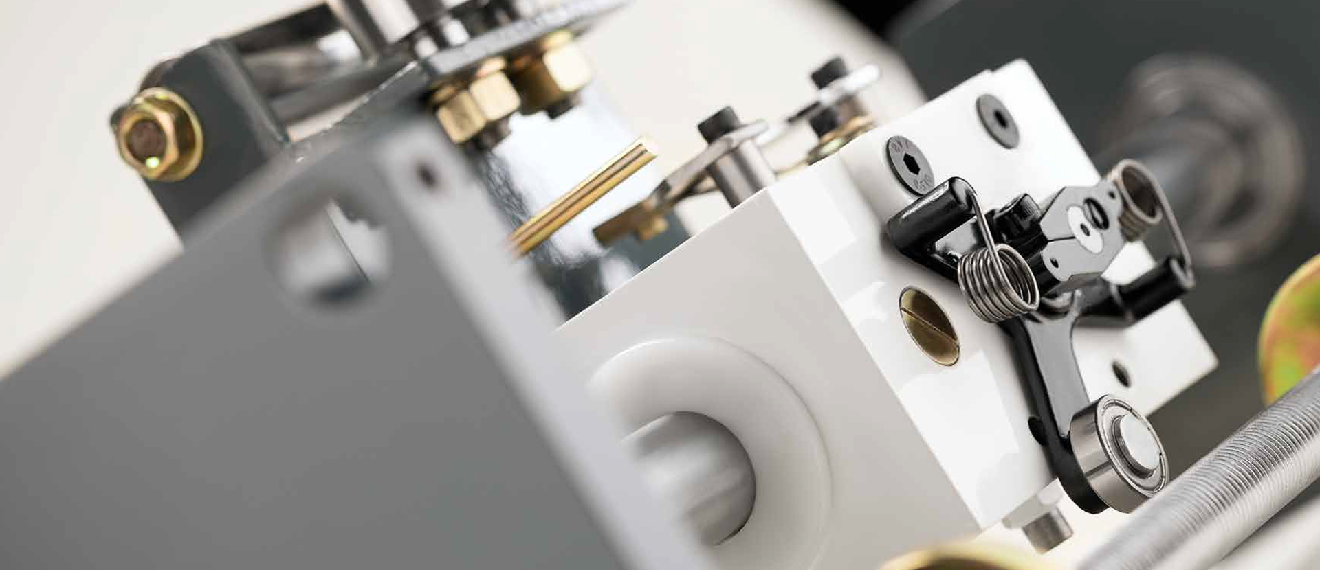
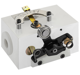
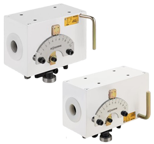
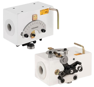
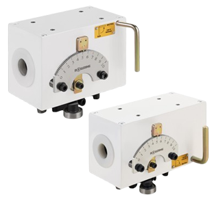
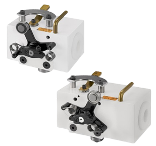
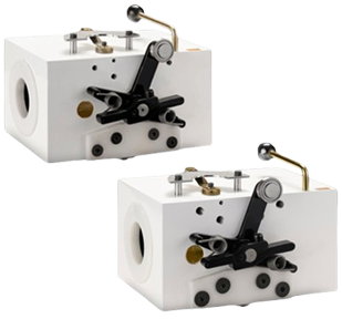
Traverse Unit
Leveraging the skills of our qualified team of professionals, we are instrumental in manufacturing and exporting a wide range of Traverse Unit. This Traverse Unit is quality approved.
Rollring Industries
Linear Drive Nut
Prominent & Leading Manufacturer from Kozhikode, we offer rrld16 linear drive nut, rrld15 linear drive nut, rrld30 linear drive nut, rrld 25 linear drive nut, rrld 20 linear drive nut and linear drive nut.
Rollring Industries
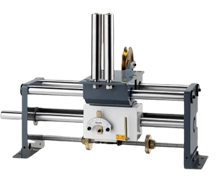
Machines
Spooling Machine, Rewinding Machine, Pay off Stand, Swift type pay off, Rewinding Machine for CO2 wire, Coiling machine for small coil, Recoiler for Stainless steel strip etc...